

Recently, there has been the invention of motorized TV lifts though they have been costly and only designed for a certain range of TVs. In addition, it has been a challenge if the TV size or installation location did not match these parameters. However, it is now possible to construct a custom TV lift using the available extensive range of DIY consumer electronics. This article discusses the simplified procedure of installing a motorized TV lift.
Choose a linear actuator
Linear actuator can be described as an electric motor connected to a track and a worm drive. Applying a power of 12v in one direction makes a bracket on the worm drive to ascend up the track. On reversing the voltage, the bracket descends down the track. Actuators are available in various weight capacities as well as stroke length, making them very useful for a variety of material conveyance. In order to choose the appropriate linear actuator, consider the one with more than 50% weight capacity than the TV as well as a stroke length of at least 1 to 2 inches longer than the TV height. One should also be keen on the operating speed. A bracket kit is offered by most manufacturers, thereby simplifying the TV mount attachment.

Choosing a switch
Only a double pole double throw (DPDT) switch rated 12v and 10 amps because the wiring is a simple 12v positive and negative pair. By flipping the switch up or down the TV is moved up or down respectively. To make the wiring easier, a still installation is used and a remote control unit was selected. The maximum amp draw for the chosen linear actuator (see more on the page) should be determined as well as a 12v wall plug transformer with a rating of over 50 percent actuator amperage. A 10-amp transformer can be used. This system ensures that only 12v is supplied beyond the wall outlet, this makes it easier and safe installation among most Dyers.

Installing the actuator
The actuator should be positioned at the center behind the TV. All studs should be put facing the actuator location, ensuring that all electrical wiring around are temporarily deactivated by a certified electrician. The drywall is removed from inside the face of the adjacent studs, this exposes the cavity and the width of the studs as well as the height of the actuator. In case the installation is on an exterior wall and there is enough cabinet depth, the actuator should be installed on the wall to avoid displacement of insulation. A blocking and a piece of 5/8” plywood across the cavity, the depth-wise is located to ensure that the actuator protrudes at least 3/4” from the wall. Next, the height-wise should be located such that the bracket in the up position is very close to the top enclosure. Fix the actuator into the plywood using wood screws.
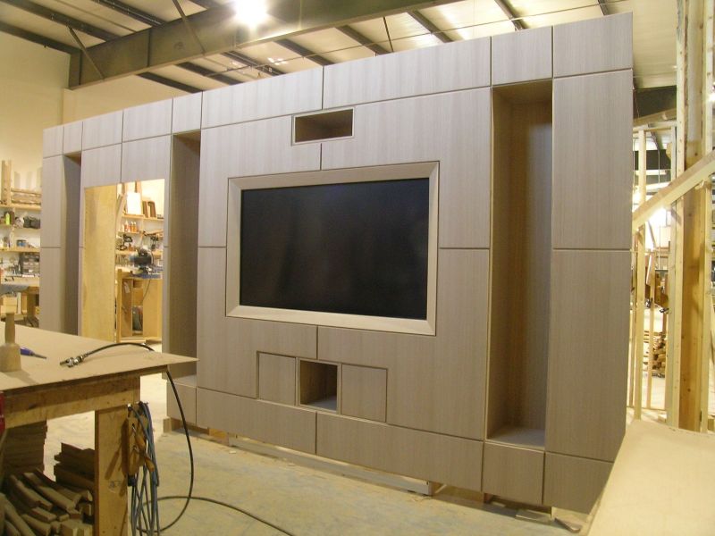
Making an operable door
The piano hinge is installed in the mantel top such that a 4” x 30” piece of plywood which is painted would close over the TV when retracted. To prevent the door having direct contact with the plastic bezels, felt pads are added.

Create a mounting plate and install the TV
A mounting plate between the actuator bracket and the TV is made using a piece of plywood. A large piece of cardboard is used to make a template that covers the real TV screw holes. Add 1/2” after measuring the bottom of the actuator lift bracket to the top of the operable door in the open position. To avoid the damage to the TV, it is advisable to install a wood block on the TV mounting plate to ensure that the door is open once the TV passes.
Finalizing
Make sure that all screws and bolts are tight. Fix all cords and cables to allow the flexibility of the TV. Perform the test for the lift operation and TV. If well planned, the installation can be completed in one day.
Picture credits:
Figure 1. Linear actuator. (source: http://cdn.shopify.com/s/files/1/0813/8299/products/M-D4_Linear_Actuator_01_-_For_Fb_Ad_4d50dd07-5ece-43f2-aad0-47cf8da7a5b9.jpg?v=1433443275)
Figure 2. Double pole double throw (DPDT) switch. (source: http://s24.photobucket.com/user/Sean91_/media/5192d125.jpg.html)
Figure 3. Double pole double throw (DPDT) switch (source: http://www.woodweb.com/knowledge_base_images/bah/TV_concealment_door_ideas_04.jpg )